

Ich bin im E34 de seit 2005 Mitglied (unter anderem Namen als hier) und aktiv da und hab auch viel an Infos da hochgeladen. Da ist zwar weniger Traffic heutzutage, aber wenn man Fragen hat, dann bekommt man detaillierte Antworten, speziell auch wenn es um Elektrik/Elektronik geht. Und das geballte Wissen um den E34 ist da wohl einmalig konzentriet, siehe auch was wir da unter FAQ alles zusammengetragen haben an Infos und technische Unterlagen hochgeladen haben.
Beiträge von shogun
-
-
Hier in Japan war es frueher so, dass alle Autos ueber 10 Jahre alt jedes Jahr zum TÜV mussten, da das mit erheblichen Kosten einher ging wegen genauer Vorschriften, was getauscht werden musste (egal ob defekt oder nicht, einfach nach Liste), war es ueblich die Autos ueber 10 Jahre Alter zu verkaufen fuer den Export. Das hat man geaendert, seit Jahren ist es jetzt so: Nach Neuzulassung erster TÜV nach 3 Jahren, dann alle 2 Jahre.
Auch sinnloses Tauschen nach Liste hat sich erledigt, da wurden Teile getauscht nach paar TSD KM,da in der Liste aufgefuehrt, egal ob notwendig oder nicht.
Frueher konnte man auch nicht selber zum TÜV , ging nur ueber zugelassene Werkstaetten, die nach Liste tauschten, heutzutage kann man auch das selber machen. Video wie das heute geht") https://www.youtube.com/watch?v=ns7g9EmmE7g
https://www.youtube.com/watch?v=ns7g9EmmE7g
die Gewichtssteuer muss man immer noch alle 2 Jahre zahlen. Aber das ist ja noch nicht alles, Autobahngebuehren sind hoeher als Spritkosten, Autos duerfen nur angemeldet werden, wenn sie einen Parkplatz nachweislich haben im Umkreis von 2 Km der Wohnung. Da kommt vor der Anmeldung extra ein Pruefer vorbei. -
Cabrio, Limo, Compact...? Mit CC oder ohne? Baujahr? Les mal diesen Thread Steckerbelegung Rückleuchte beim Cabrio und bei Limo
-
Hier mal ein Video von einer defekten Membrane in einem Benzindruckregler, 1997 Buick 3.8 Ltr V6, ab 1 Minute 50 wird es interessant, Vakuumschlauch abgezogen, dauert ca. 2 Minuten, ab Minute 4 sifft es, Testing for a leaking, ruptured, fuel pressure regulator diaphragm
Externer Inhalt www.youtube.comInhalte von externen Seiten werden ohne Ihre Zustimmung nicht automatisch geladen und angezeigt.Durch die Aktivierung der externen Inhalte erklären Sie sich damit einverstanden, dass personenbezogene Daten an Drittplattformen übermittelt werden. Mehr Informationen dazu haben wir in unserer Datenschutzerklärung zur Verfügung gestellt. -
Nimm Deine VIN und geb sie in den ETK ein, unter Sub Sektion Motor findest Du die richtige Teilnummer und auch die Zeichnung, lt ETK wird 11521740962 eingesetzt bei Motor M43, M40, M42, M44, M50, M52 am E36, und der hat 4 Schrauben
Hat der einen Zusatzluefter? http://de.bmwfans.info/parts-c…acitor_additional_blower/ der Zusatzluefter hat 2 Stufen. bei Klima an laeuft er immer mit in Low , am Kuehler sitzt in Temperaturschalter 91 - 99 Grad Celsius, schaltet dann um, wenn Temperatur erreicht ist auf hohe Drehzahl http://de.bmwfans.info/parts-c…tor_expansion_tank_frame/
Wird ueber 2 Relais geschaltet Low und Hi, beide sind abgesichert mit Sicherungen, Testen kann man es wie hier gezeigt beim E32 http://www.nmia.com/~dgnrg/page_20.htm Stromlaufplan E36, aber das siehste alles im Detail E36 Schaltpläne
Zusatzluefter springt auch an, auf Low, wenn 91 Grad da sind. Wenn 99, dann auf Hi speed.
-
hab mal einen 03/1995 328i Automatik genommen, da waere das dies http://de.bmwfans.info/parts-c…_system_fan_fan_coupling/ suche selber im Teilekatalog mit der VIN Deines Fahrzeuges. Wenn das Auto extremen Bedingungen ausgesetzt ist wie Berge oder super warme Gegend, kannste die Australien = Tropenausfuehrung nehmen, Luefterblatt hat 10mm mehr Durchmesser, und Tropen Visco gibt es auch. Die normale Behr hat Nr. 11521740962 , bei daparto de gibt es die Preise von EUR 30 - ~ 280 fuer Mahle Behr, sollte 4 Schrauben haben.
-
neueste Liste zugelassene Oele von ZF 1.4.2025 https://aftermarket.zf.com/lubricants/en/te-ml_11-en.pdf
According to marking:
- Transmissions with black type plate
Automatic Transmission Fluid (ATF) according to lubricant class 11B
=> Refer to the following pages for approved commercial products
- Transmissions with green type plate or with green label on the oil pan.
ZF LifeguardFluid 5 (ZF No. S671 090 170), (ZF approval number ZF001363)
=> BMW Oil No. 8322 9407807
ATF according to lubricant class 11B are not permitted (exception: ZF LifeguardFluid 5)
Ravenol ist zwar glaub nicht auf der Liste, aber wird oft empfohlen https://www.ravenol.de/de/prod…e/ravenol-atf-54-hp-fluid
RAVENOL ATF 5/4 HP Fluid ist ein ATF (Automatic Transmission Fluid) für alle 4- und 5-Gang-Automatikgetriebe von ZF. Garantiert in jedem Betriebszustand ein Maximum an Verschleißschutz. RAVENOL ATF 5/4 HP Fluid hat eine neutral braune Farbe.
Anwendungshinweise: RAVENOL ATF 5/4 HP Fluid ist geeignet für den Einsatz in Automatik-Getrieben der ZF Serie 4 HP (4HP20, 4HP22, 4HP24) und 5HP (5HP18, 5HP19, 5HP24, 5HP30).
-
ZF 5HP18 = BMW Bezeichnung A5S310Z hat Waehlschieber ZF 1056.327.173 Teilnr. Anleitung Englisch ATF auffuellen und Anzugsdrehmomente https://www.thectsc.com/5hp18-…on-fluid-level-procedures
A) Transmissions Fluid Level Checking
1) The transmission fluid temperature must be between 30°C and 35°C before checking can begin. Use test equipment to determine the trans temperature.
2) The vehicle must be level with engine running at idle speed and air conditioning turned on.
3) Step on the brakes firmly, apply parking brake fully and shift to D and R, briefly pausing in each position before shifting back to the Park position.
4) With the engine running at idle speed and the selector in Park position, remove the filler plug. Monitor the transmission temperature, if a small stream of oil runs out at 40°C, the fluid level is correct.
5) If no oil runs out when the filler plug is removed, the fluid level is too low and oil needs to be added until it overflows.6) With engine running, install the oil filler plug and tighten to proper torque.
B) Adding fluid after repairs1) With the engine stopped and the transmission in Park position, remove the oil filler plug. Add transmission fluid until a small stream of oil runs out.
2) Insert the filler plug and tighten by hand. Start the engine.
3) With the engine running, remove the oil filler plug and add transmission fluid until a small stream of oil runs out. Insert the filler plug and tighten by hand.
4) Follow the “Transmission fluid level checking” procedure described in section A) above.C) Notes on fluid level and adding procedure
1) Use ZF-LifeguardFluid5 - the Shell LA-2634 is no longer available.
2) If the transmission temperature rises above 50°C during the fluid level checking procedure the resulting oil level will be to low. Let the transmission cool down and repeat the fluid level procedure.3) Have transmission fluid and a suitable oil pump available before starting the fluid level procedure. The transmission fluid temperature will rise quickly during the checking procedure.
--------------------------------------------------------------------------------------
A) Getriebeölstandskontrolle
1) Die Temperatur der Getriebeflüssigkeit muss zwischen 30°C und 35°C liegen, bevor mit der Prüfung begonnen werden kann. Verwenden Sie ein Testgerät, um die Getriebetemperatur zu bestimmen.
2) Das Fahrzeug muss waagerecht stehen, der Motor muss mit Leerlaufdrehzahl laufen und die Klimaanlage muss eingeschaltet sein.
3) Treten Sie fest auf die Bremsen, ziehen Sie die Feststellbremse vollständig an und schalten Sie in D und R. Halten Sie in jeder Stellung kurz inne, bevor Sie in die Parkstellung zurückschalten.
4) Entfernen Sie die Einfüllschraube, während der Motor im Leerlauf läuft und der Wählhebel in der Parkstellung steht. Überwachen Sie die Getriebetemperatur. Wenn bei 40°C ein kleiner Ölstrahl ausläuft, ist der Ölstand korrekt.
5) Wenn beim Entfernen der Einfüllschraube kein Öl ausläuft, ist der Flüssigkeitsstand zu niedrig und es muss Öl nachgefüllt werden, bis er überläuft.
6) Setzen Sie bei laufendem Motor die Öleinfüllschraube ein und ziehen Sie sie mit dem richtigen Drehmoment an.
B) Nachfüllen von Flüssigkeit nach Reparaturen
1) Entfernen Sie bei abgestelltem Motor und Getriebe in Parkstellung die Öleinfüllschraube. Getriebeöl einfüllen, bis ein kleiner Ölstrahl austritt.
2) Setzen Sie die Einfüllschraube wieder ein und ziehen Sie sie mit der Hand fest. Starten Sie den Motor.
3) Bei laufendem Motor die Öleinfüllschraube entfernen und Getriebeöl einfüllen, bis ein kleiner Ölstrahl austritt. Setzen Sie die Einfüllschraube wieder ein und ziehen Sie sie mit der Hand fest.
4) Befolgen Sie das Verfahren zur Überprüfung des Getriebeölstands, das in Abschnitt A) beschrieben ist.
C) Hinweise zum Flüssigkeitsstand und Nachfüllverfahren
1) Verwenden Sie ZF-LifeguardFluid5 - das Shell LA-2634 ist nicht mehr erhältlich.
2) Steigt die Getriebetemperatur während der Ölstandskontrolle auf über 50°C, so ist der Ölstand zu niedrig. Lassen Sie das Getriebe abkühlen und wiederholen Sie die Ölstandskontrolle.
3) Halten Sie Getriebeöl und eine geeignete Ölpumpe bereit, bevor Sie mit der Ölstandskontrolle beginnen. Die Temperatur der Getriebeflüssigkeit steigt während des Prüfvorgangs schnell an.
------------------------------
Gesamtmenge ATF mit Wandler ist 7.8 Ltr., ohne Wandler 3.2 Ltr. , Der Wandler wird ja nicht leer bei der Aktion, rechne mal mit 3-4 Ltr, aber die genaue Menge ergibt sich dann bei der Fuellprozedur . Achte auf die Temperatur, 30 Grad ist besser als 35 Grad, es geht mehr ATF rein, also je kaelter um so mehr Liter Volumen
https://www.europeantransmission.com/Bulletin/DTC.BMW/BMW%20transmissionfluidchard.pdf
Hier ein guter Youtube 24 Minuten, Diagnose Automatikgetriebe, Schulungs- und Informationsprogram A5S 310 Z = 5HP18, ab Minute 6 wird es interessant, was eine zu niedrige Oelfuellung ausmachen kann, welche Geraeusche usw. Wie richtig auffuellen.
Externer Inhalt www.youtube.comInhalte von externen Seiten werden ohne Ihre Zustimmung nicht automatisch geladen und angezeigt.Durch die Aktivierung der externen Inhalte erklären Sie sich damit einverstanden, dass personenbezogene Daten an Drittplattformen übermittelt werden. Mehr Informationen dazu haben wir in unserer Datenschutzerklärung zur Verfügung gestellt. -
wenn der Wahlhebel gebrochen ist, kann man nichts machen, es gibt keine Notentriegelung. Das Auto muss abgeschleppt werden mit einem Abschlepp-Dolly. Ein Abschlepp-Dolly stützt die Hinterräder des Fahrzeugs, während ein Abschleppfahrzeug die Vorderräder stützt.
Wenn allerdings der Wahlhebel nicht gebrochen ist und nur der Seilzug gerutscht ist/gebrochen, dann kann man den Seilzug loesen und dann mit einer Zange direkt am Getriebe Wahlhebel was aendern auf N, P etc
http://de.bmwfans.info/parts-c…t_automatic_transmission/ aber Du weist ja erst, was defekt ist, wenn der Wahlhebel ausgebaut ist bzw Du den Seilzug und die Einstellung untersucht hast.
Also geht nur ein Abschlepp-Dolly, ab in die Werkstatt und auf die Buehne und das Teil ausbauen
-
https://www.leebmann24.com/de/…etriebe-automatisch-10107
ZF 5HP18 = BMW Bezeichnung A5S310Z hat Waehlschieber ZF 1056.327.173 Teilnr. gleich fuer diese ZF: 5HP18 5HP19, 5HP24A, 5HP30 .schau vorsichtshalber noch mal auf den seitlichen Sticker am Getriebe, ob da ZF 5HP18 drauf steht, und notier Dir sofort auch die ZF Herstellerseriennummer, sitzt direkt ueber der Oelwanne. Waehlschieber kannste im net kaufen von ZF Teilelaeden oder daparto, ebay etc pp, nicht BMW
-
gib mal die komplette VIN = 17-stelligen Code an, nicht nur die letzten 7 Zahlen. Kannst auch selber nachschauen z B bei Leebmann im Teilekatalog, der ist up to date, nicht so wie die online ETK https://www.leebmann24.com/de/de Teil 24341422340 ist fuer ein Automatikgetriebe A5s300j , http://bmwfans.info/parts-cata…s_control_unit#1422340_10 A5js300j ist ein JATCO Getriebe, Welches Getriebe ist denn bei Dir eingebaut? Ist ja ein Typenschild dran seitlich. JATCO oder ZF? Wenn solche Fragen sind, IMMER die komplette VIN angeben, sonst kann man nur in der Glaskugel lesen und keine korrekte Antwort geben.
Wenn ich online nachschau nach 325i Limo, Europa, Automatik, 03/1993, dann hat das ein Getriebe A5s300j und der Waehlschieber hat die BMW Nr. 24341422340
Ein ZF 5HP18 = BMW Bezeichnung A5S310Z hat Waehlschieber ZF 1056 327 173 Teilnr. ist gleich fuer diese ZF:
5HP18-5HP18A-5HP19-5HP19FL-5HP19FLA-5HP19HLA-5HP24-5HP24A-5HP30
-
hab mal weiter gesucht, hier ist noch ein uralter Thread mit paar Bildern, evtl. hilft das was https://bmw-forum.de/forum/3er…3%B6ffnet-sich-nicht-mehr
-
Da die Links nicht mehr gehn, hier neu, beim Cabrio muss auch keine Tuerpappe innen ab, das Lock ist unter der Plastikabdeckung seitlich an der Tuer
https://bimmertips.com/wp-content/uploads/2018/02/E36_E34_Door_Handle_Seal_Replacment_02.jpg
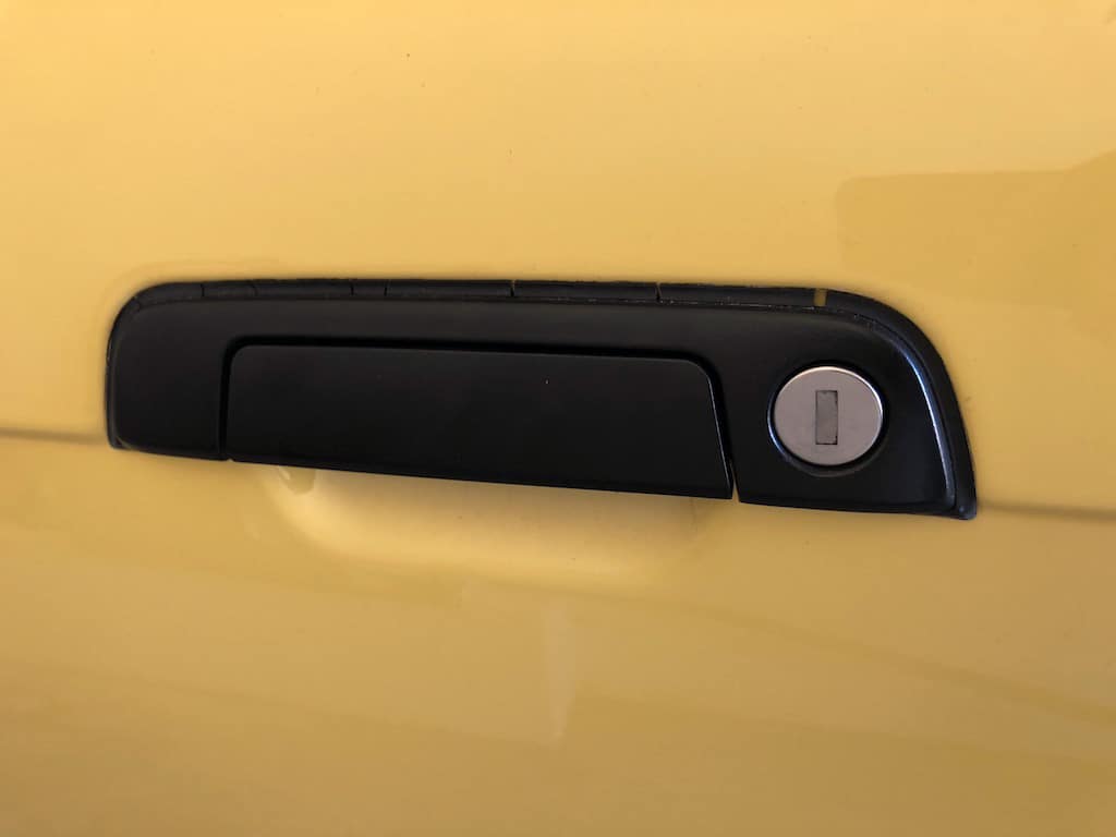 BMW Seal Replacement, Door Handle E36 E34 E32Problem: Cracked, weathered, missing door handle seal. Application: All BMW E36 & E34 models. Solution: Remove and replace. Cost: $26 per door Where tobimmertips.com
 -
Bist Du da schon weiter gekommen? Falls das Problem geloest wurde, lass es uns wissen.
-
schau noch mal in den ETK, ob die Ruecksitze nicht ausgebaut werden koennen und man dann in den Kofferraum kommt. Ich kenne leider das Cabrio nicht im Einzelnen, aber im E36, E34, E32 gab es Skisaecke, da ist original die Trennwand/-blech zwischen Innenraum und Kofferraum perforiert, kann man leicht mit dem Hammer ausschlagen und kommt dann in den Kofferraum vom Innenraum.
-
als ersten Schritt mal die Teilnummern im ETK vergleichen fuer beide Modelle
-
nein, lad es dir da runter, musst Dich aber anmelden bei scribd, die haben 30 Tage kostenlose downloads
-
um was fuer einen E36 handelt es sich denn? Limo, Cabrio, Coupe, Compact, Touring? Baujahr/Monat?
Schau mal hier ab Seite 7 https://www.scribd.com/doc/42637817/BMW-Tricks-Tips
-
geh mal hier durch die originalen Daten von BMW, die ich mal gepostet hab, engine specifications, machining limits engine specifications, machining limits
-
neues von der Gartenfront : 4-Takt Rasenmaeher ist nach dem Winter wieder angesprungen mit dem Rest alten Sprit (ohne Stabilisator) im Tank vom letzten Jahr, allerdings recht wiederwillig. Neuen Sprit nachgefuellt zum Mischen, das merkte man an der Zuendwilligkeit.
Bei den 2-Taktern fuer Laubblasen, Heckenschere, Kettensaege mach ich es nach Empfehlung von Stiehl: Entleeren Sie den Tank Ihrer Heckenschere. Lassen Sie die Heckenschere anschließend laufen, bis der Vergaser leer ist. Grund dafuer ist, das sonst die Dichtungen im Vergaser schnell kaputt gehn, sind ja auch teilweise Benzinpumpenmembranen
das kann ich fast schon im SchlafExterner Inhalt www.youtube.comInhalte von externen Seiten werden ohne Ihre Zustimmung nicht automatisch geladen und angezeigt.Durch die Aktivierung der externen Inhalte erklären Sie sich damit einverstanden, dass personenbezogene Daten an Drittplattformen übermittelt werden. Mehr Informationen dazu haben wir in unserer Datenschutzerklärung zur Verfügung gestellt.